






Skip to content

Evaluation PCB for the PLD Series Laser Diode Drivers

    • 1 - 5 each
      $173.00
    • 6+ each
      $173.00
      $170.00

    Contact Factory for High Volume Pricing
    Price adjustments will be reflected in the cart. For availability information please contact us.

    All prices are in US dollars. Prices do not include shipping charges. All prices will be confirmed at time of shipment and may include pass-through tariff estimates.

    If ordering from or shipping to AustraliaChina, or Hong Kong, please contact your distributor.

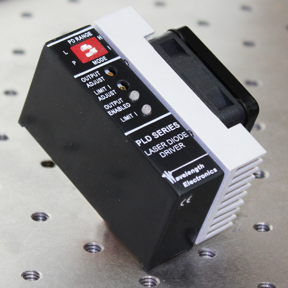
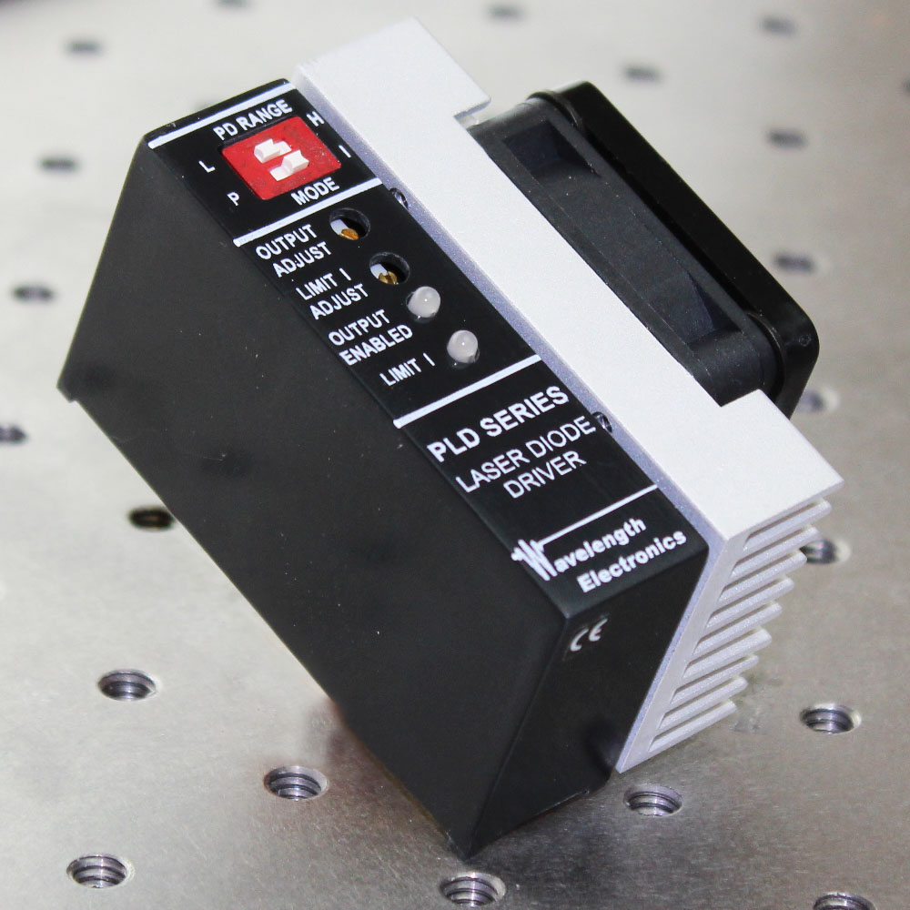
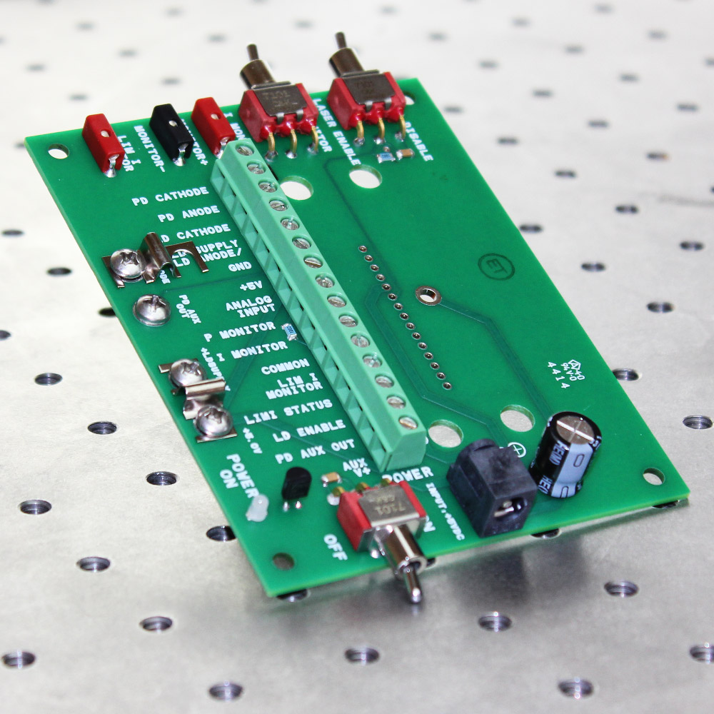
    The PLDEVAL is an evaluation board for some of the PLD Series Laser Diode Drivers: PLD6500, PLD5000PLD1250PLD500, or PLD200. It simplifies benchtop operation of the PCB mount drivers and reduces prototyping time. This evaluation board does not include the laser diode driver itself. It includes a terminal strip for easy wiring to the power supply and laser diode. DVM cable ready test points monitor the setpoint, current limit, and photodiode signal voltages. These voltages are also on the terminal strip along with the LD Enable and Modulation inputs. Onboard switches select main power on, enable / disable, and whether the DVM point monitors laser or photodiode current. An LED indicates when main power is on. A shorting bar ties the high compliance input to +5 V. It can be removed for high compliance voltage operation. Note that the laser diode driver internal electronics require +5 V maximum input. The PLDEVAL is CE certified. A PDF version of the Declaration of Conformance is available. Free, effective, and responsive technical support is available to simplify integration of Wavelength products into your OEM design. Standard product can be easily modified to meet your application requirements.

    Size: 3.4 x 4.4 x 2.34″ (with PLD installed)
    86 X 112 x 59 mm

    Top View of PLDEVAL
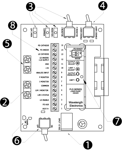
    Top View of PLDEVALPCB

    1- +5 V Input – Either use the 2.5 mm DC input jack or pins 10 & 11 on the terminal strip for +5 V input. We recommend 18 AWG wire for the power and laser diode connections.
    2- LD Supply Shorting Bar – This jumper ties +LD Supply to +5 V (default from factory). For higher compliance voltage, remove the jumper and use pin 12 on the terminal strip for the high compliance voltage.
    3- Monitors – Test points allow you to monitor Limit Current and either Laser Diode or Photodiode Current based on the Monitor Switch position.
    4- Enable / Disable Output Current – Once DC power is applied, this switch either enables or disables laser diode current. Toggle this switch to clear a Current Limit error.
    5- Laser Type Jumper – This jumper is used with Type C laser diodes only. By default it is not installed at the factory.
    6- Power On – This switch applies DC power to the PLD. The Green LED will light when DC power is applied.
    7- Mechanical Support / Grounding Screw – A tapped hole in the heatsink accepts a 4-40 x 1/4 screw from the bottom of the PCB. Grounding the heatsink with the screw will reduce fan noise on the PLD6500PLD5000 or PLD1250.
    8- Terminal Strip – We recommend 22 AWG wire to the monitors and inputs on this terminal strip.

    DATASHEETS
    MECHANICAL / CAD DRAWINGS
    SOFTWARE
    DESIGN TOOLS
    ACCESSORIES
    SKUDESCRIPTIONPRICEIMAGE
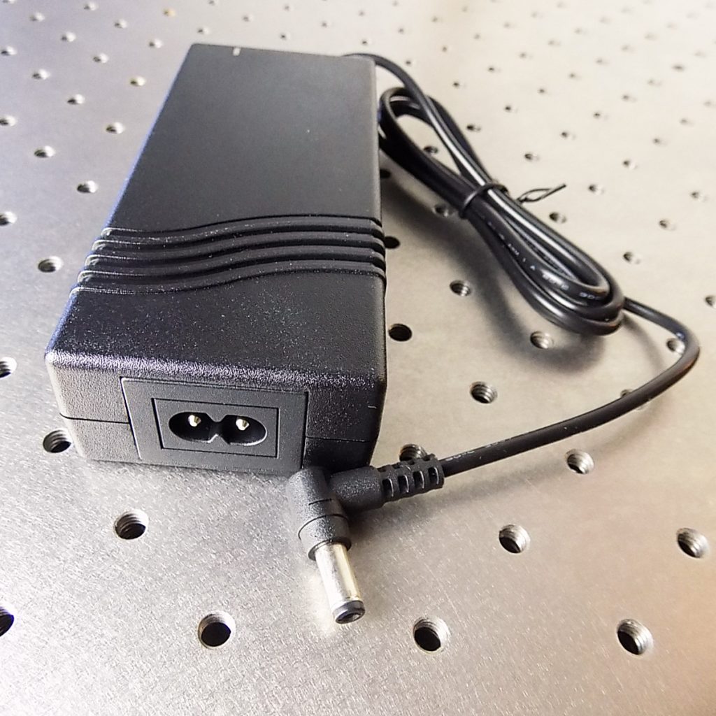
    PWRPAK-5V Switching Power Supply 6 A, 5 V $161.00
    RELATED PARTS
    SKUDESCRIPTIONPRICEIMAGE
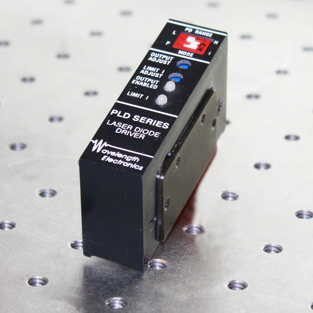
    PLD200 PLD200 200 mA Laser Diode Driver, PCB $300.00
    PLD500 PLD500 500 mA Laser Diode Driver, PCB $314.00
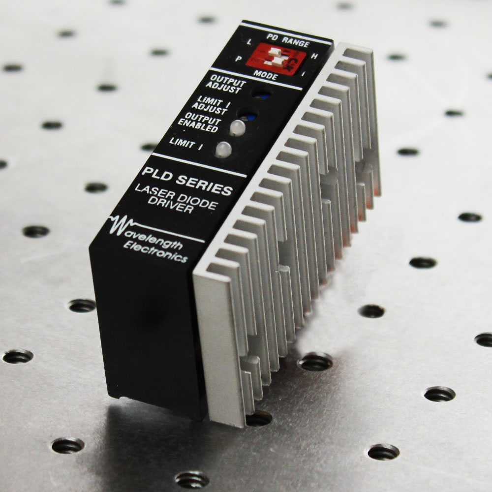
    PLD1250 PLD1250 1.25 A Laser Diode Driver, PCB $341.00
    You save (%)
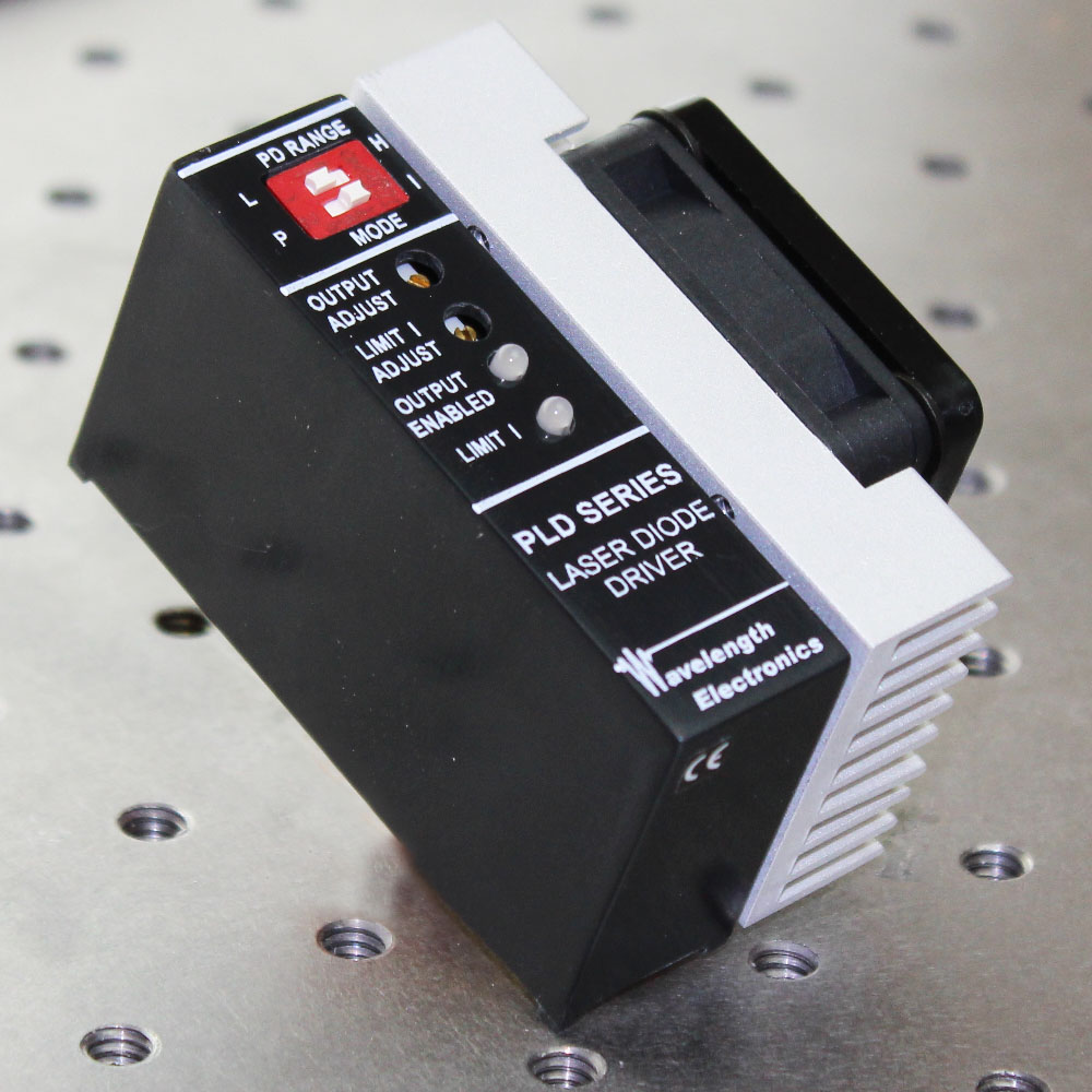
    PLD5000 PLD5000 5 A Laser Diode Driver, PCB $349.00
    You save (%)
    PLD6500 PLD6500 6.5 A Laser Diode Driver, PCB $375.00
    You save (%)

    NOT SEEING WHAT YOU NEED?