







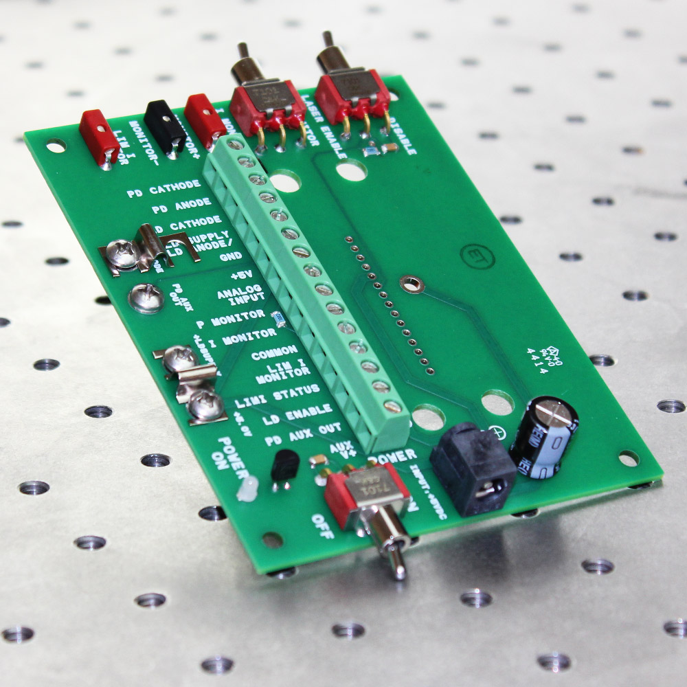
Size: 3.4 x 4.4 x 2.34″ (with PLD installed)
86 X 112 x 59 mm
Top View of PLDEVAL
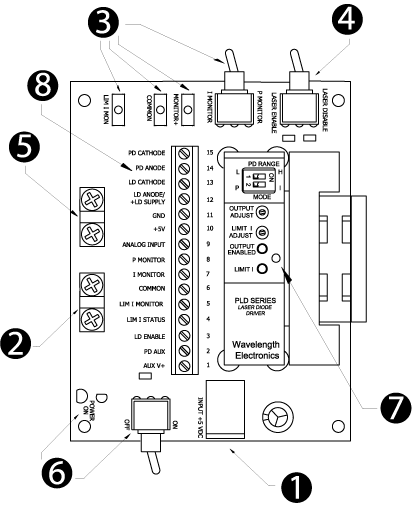
1- +5 V Input – Either use the 2.5 mm DC input jack or pins 10 & 11 on the terminal strip for +5 V input. We recommend 18 AWG wire for the power and laser diode connections.
2- LD Supply Shorting Bar – This jumper ties +LD Supply to +5 V (default from factory). For higher compliance voltage, remove the jumper and use pin 12 on the terminal strip for the high compliance voltage.
3- Monitors – Test points allow you to monitor Limit Current and either Laser Diode or Photodiode Current based on the Monitor Switch position.
4- Enable / Disable Output Current – Once DC power is applied, this switch either enables or disables laser diode current. Toggle this switch to clear a Current Limit error.
5- Laser Type Jumper – This jumper is used with Type C laser diodes only. By default it is not installed at the factory.
6- Power On – This switch applies DC power to the PLD. The Green LED will light when DC power is applied.
7- Mechanical Support / Grounding Screw – A tapped hole in the heatsink accepts a 4-40 x 1/4 screw from the bottom of the PCB. Grounding the heatsink with the screw will reduce fan noise on the PLD6500, PLD5000 or PLD1250.
8- Terminal Strip – We recommend 22 AWG wire to the monitors and inputs on this terminal strip.
| SKU | DESCRIPTION | PRICE | IMAGE |
| PWRPAK-5V | Switching Power Supply 6 A, 5 V | $161.00 | 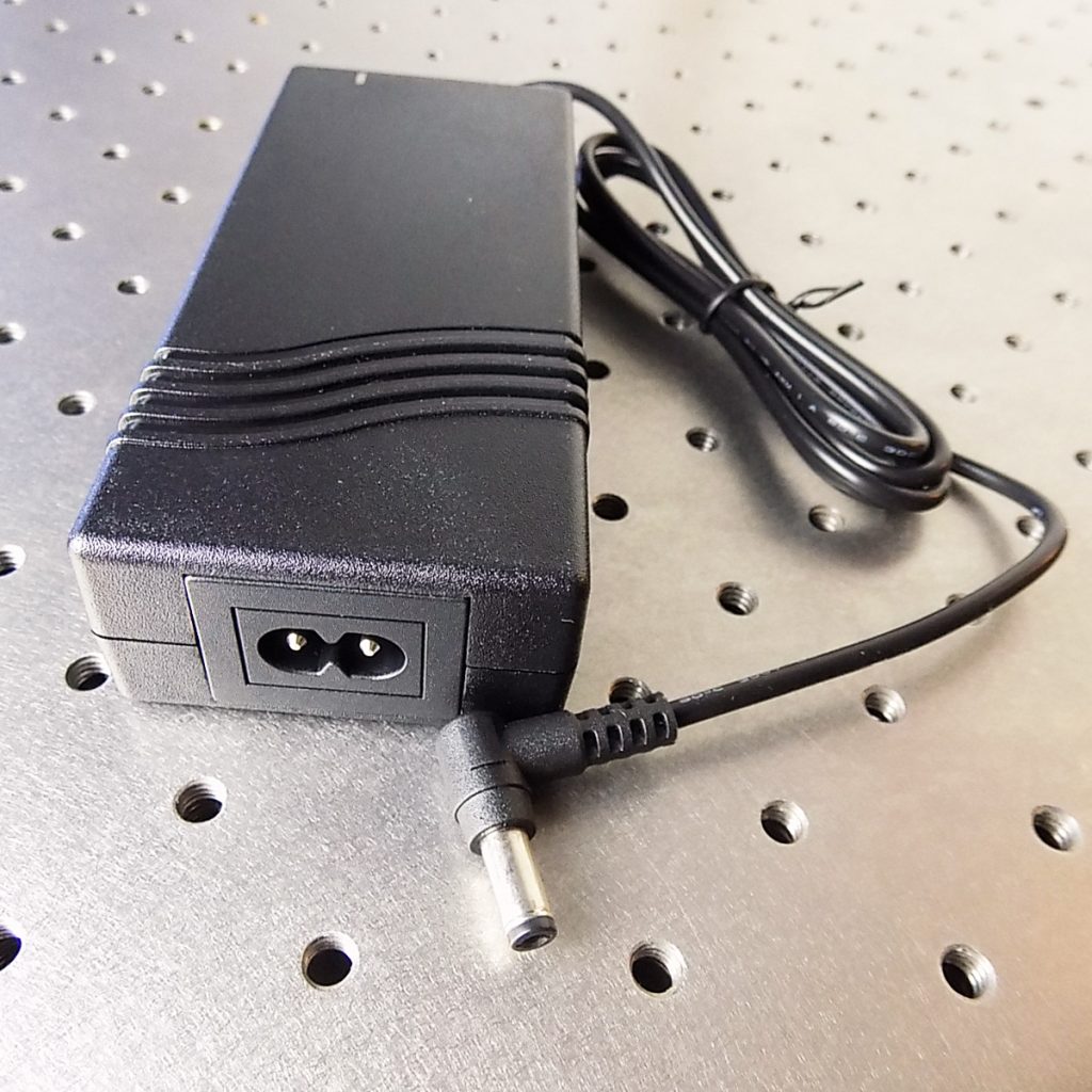 |
| SKU | DESCRIPTION | PRICE | IMAGE |
| PLD200 | PLD200 200 mA Laser Diode Driver, PCB | $300.00 | 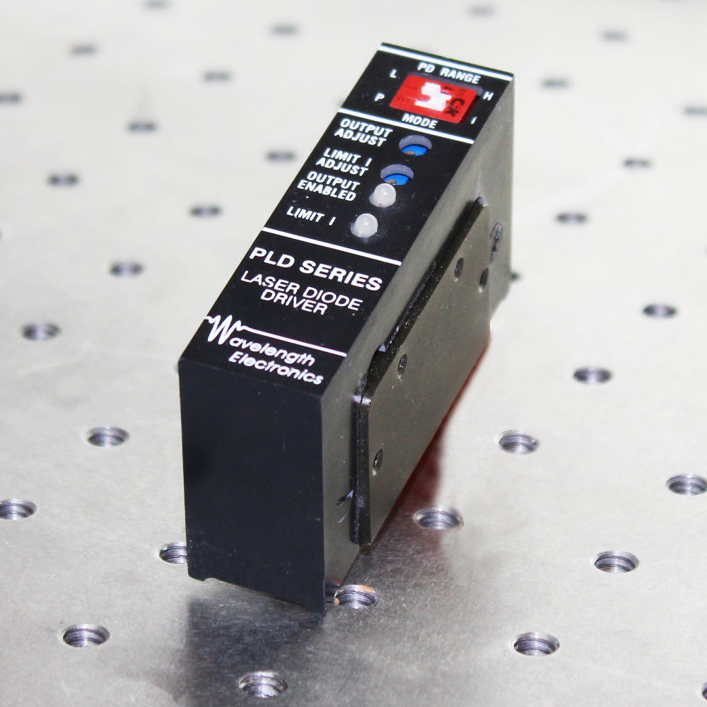 |
| PLD500 | PLD500 500 mA Laser Diode Driver, PCB | $314.00 | 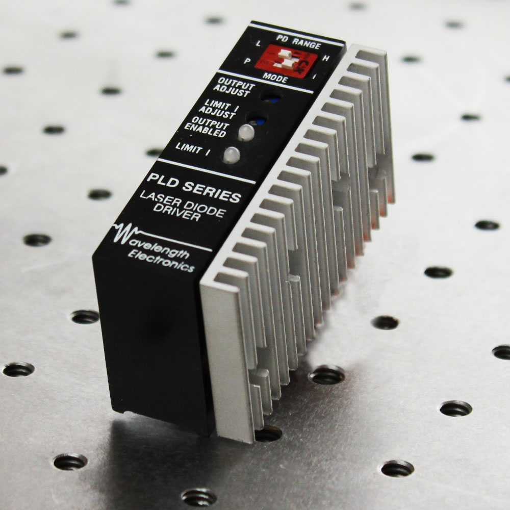 |
| PLD1250 | PLD1250 1.25 A Laser Diode Driver, PCB |
$341.00 You save (%) |
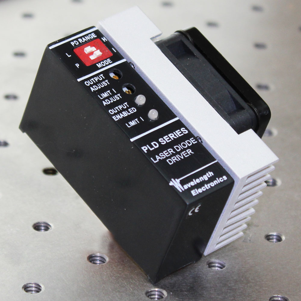 |
| PLD5000 | PLD5000 5 A Laser Diode Driver, PCB |
$349.00 You save (%) |
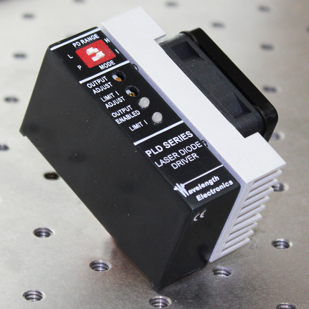 |
| PLD6500 | PLD6500 6.5 A Laser Diode Driver, PCB |
$375.00 You save (%) |
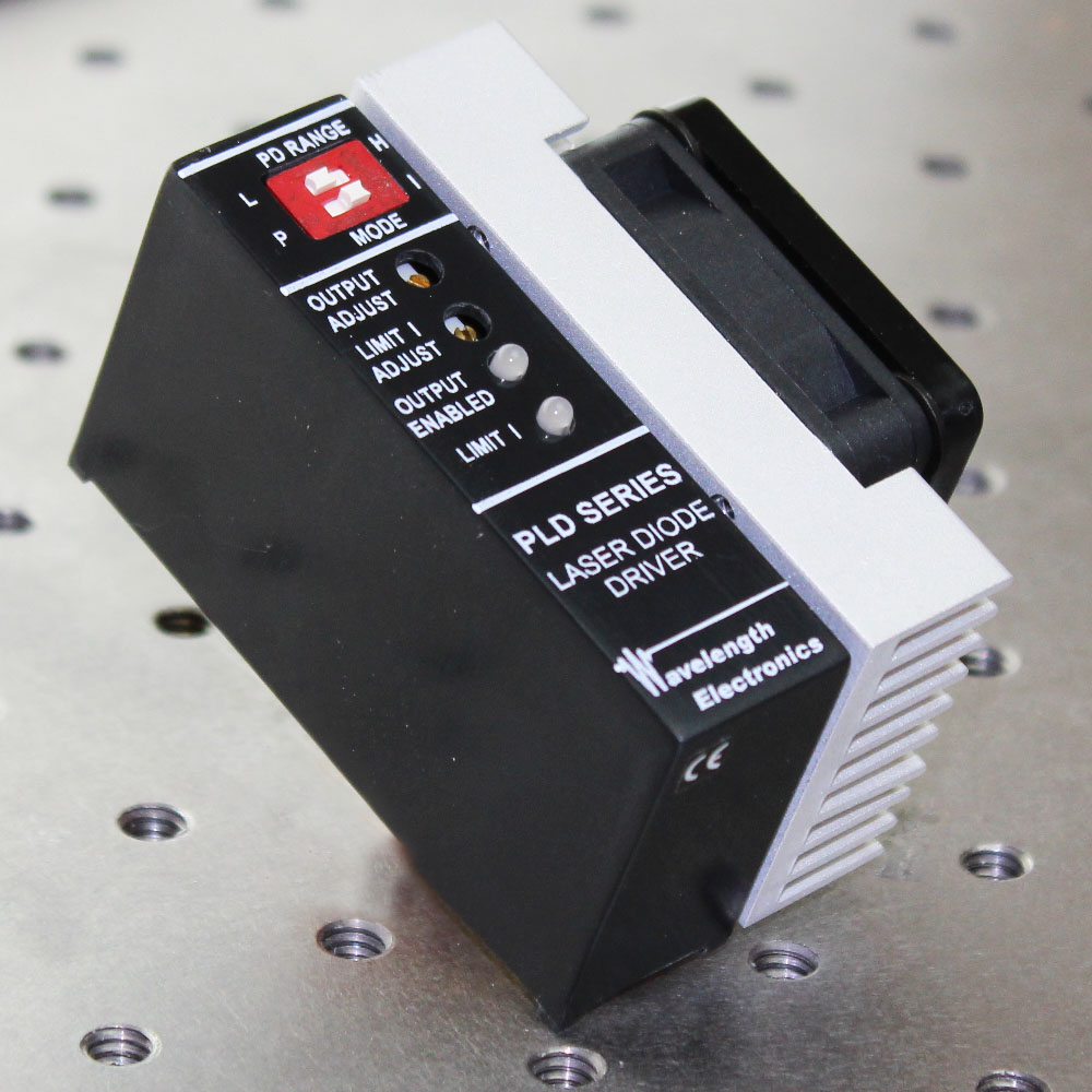 |