







SIMPLE AND FAST EVALUATION
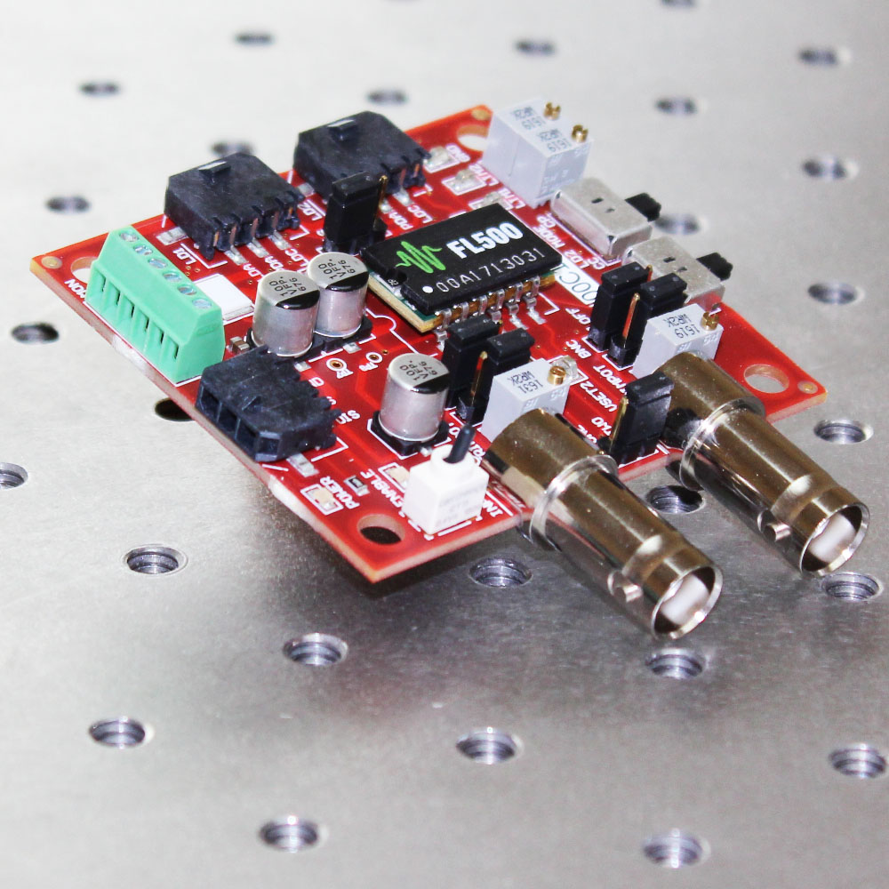
The FL591FL Evaluation Board allows you to quickly and efficiently evaluate the FL500 Laser Diode Driver and prototype your laser electronics system. The evaluation board is designed so that you can fully characterize the included FL500 — you’ll know exactly how it will perform in your application, and there will be no surprises during the development process. Ultimately, you’ll bring your system to market faster and at lower cost.DESIGNED FOR MAXIMUM VERSATILITY
The FL591FL is loaded with useful features to help simplify the prototyping process. For example, there are several setpoint-output combinations:- Two independent outputs, each driving up to 250 mA, and controlled by separate setpoint signals
- Two independent 250 mA outputs controlled by a single setpoint signal
- A single output, driving up to 500 mA
MORE PRACTICAL FEATURES
Thoughtfully designed features provide valuable benefits and protect the laser against operational anomalies:- An external signal is required to enable the output; this Enable input can be connected to a safety interlock, or coupled to a temperature controller that will disable the output if the lasers exceed a safe operating temperature.
- Drive current and photodiode current monitor outputs can be tied to an external control and monitor circuit so you can characterize every aspect of your laser control system.
- Easy access to the setpoint and current limit reference signals for design evaluation and validation of your laser control electronics.
COUNT ON WAVELENGTH ELECTRONICS
Download the brochure to view a more detailed specification chart, and then call Wavelength’s sales engineers so we can help you choose the right driver for your application. Free, effective, and responsive technical support is available to simplify integration of Wavelength products into your OEM design. Standard product can be easily modified to meet your application requirements.Supply Voltage: 3 to 9 VDC
Output Current: Two channels at 250 mA each, or 1 channel at 500 mA
Output Current Noise: 3 µA RMS
Photodiode Feedback Range: 0 to 1 mA; can be adjusted
External Modulation, 3 dB Bandwidth: 500 kHz Constant Current sine wave
Rise / Fall Time: 300 / 300 nsec to full scale
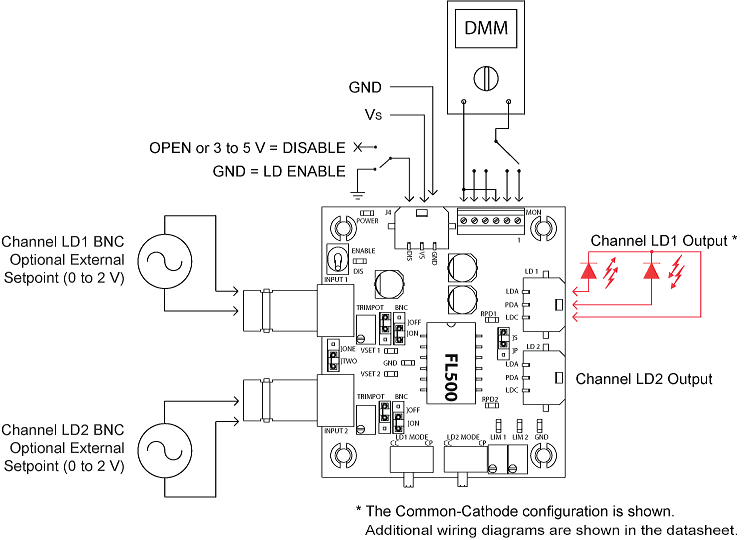
FL591FL Quick Connect Diagram
RELATED PARTS
| SKU | DESCRIPTION | PRICE | IMAGE |
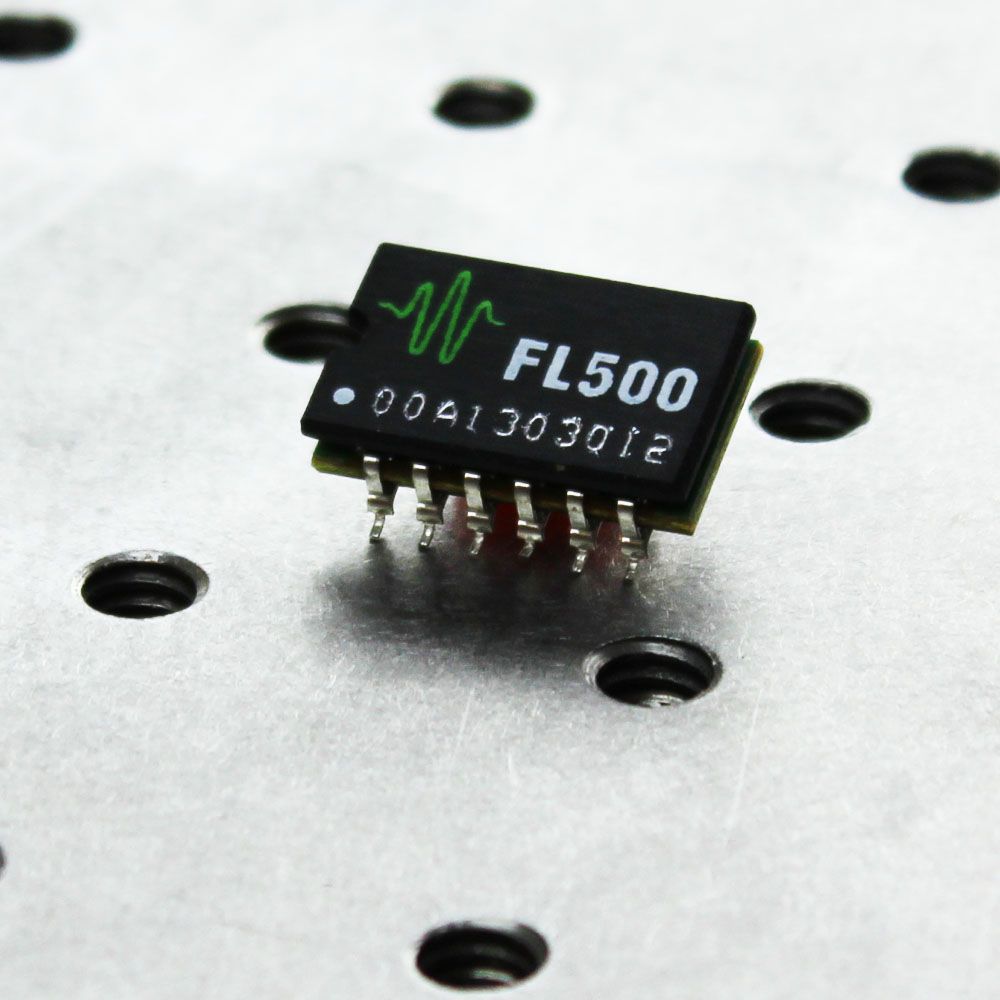
| FL500 | FL500 500 mA Laser Diode Driver |
$63.00 You save (%) |
 |