







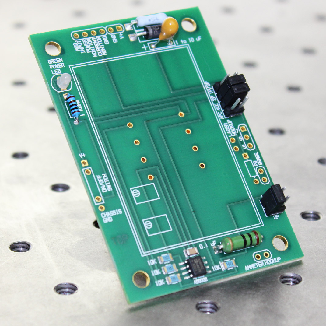
Top View of LDD P Series Evaluation Board
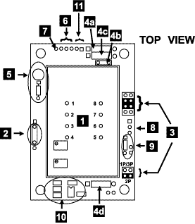
1- LDD Module – location of Laser Diode Driver component
2- Enable / Disable wire pads – Signal input to enable or disable laser diode current
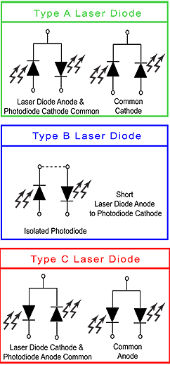
3- Jumpers – select which LDD model is installed
4a- Decoupling Resistor – Decouple the power supply
4b- Decoupling Capacitor – Decouple the power supply
4c- Transzorb – Over-voltage protection
4d- Dominant Impedance – Laser Diode over-current and transient protection
5- LED and bias resistor – Power ON indicator
6- Measurement wire pads – Measure laser diode current
7- MOD INPUT wire pads – Connect to optional signal generator for modulation or remote setpoint control
8- Laser diode wire pads – Solder laser diode cable to these pads
9- External photodiode wire pads – Monitor photodiode current while in constant laser diode current mode
10- Op-amp, four resistors, one capacitor – For operating LDD 2P in constant current mode
11- Power supply wire pads – Connections to power supply
| SKU | DESCRIPTION | PRICE | IMAGE |
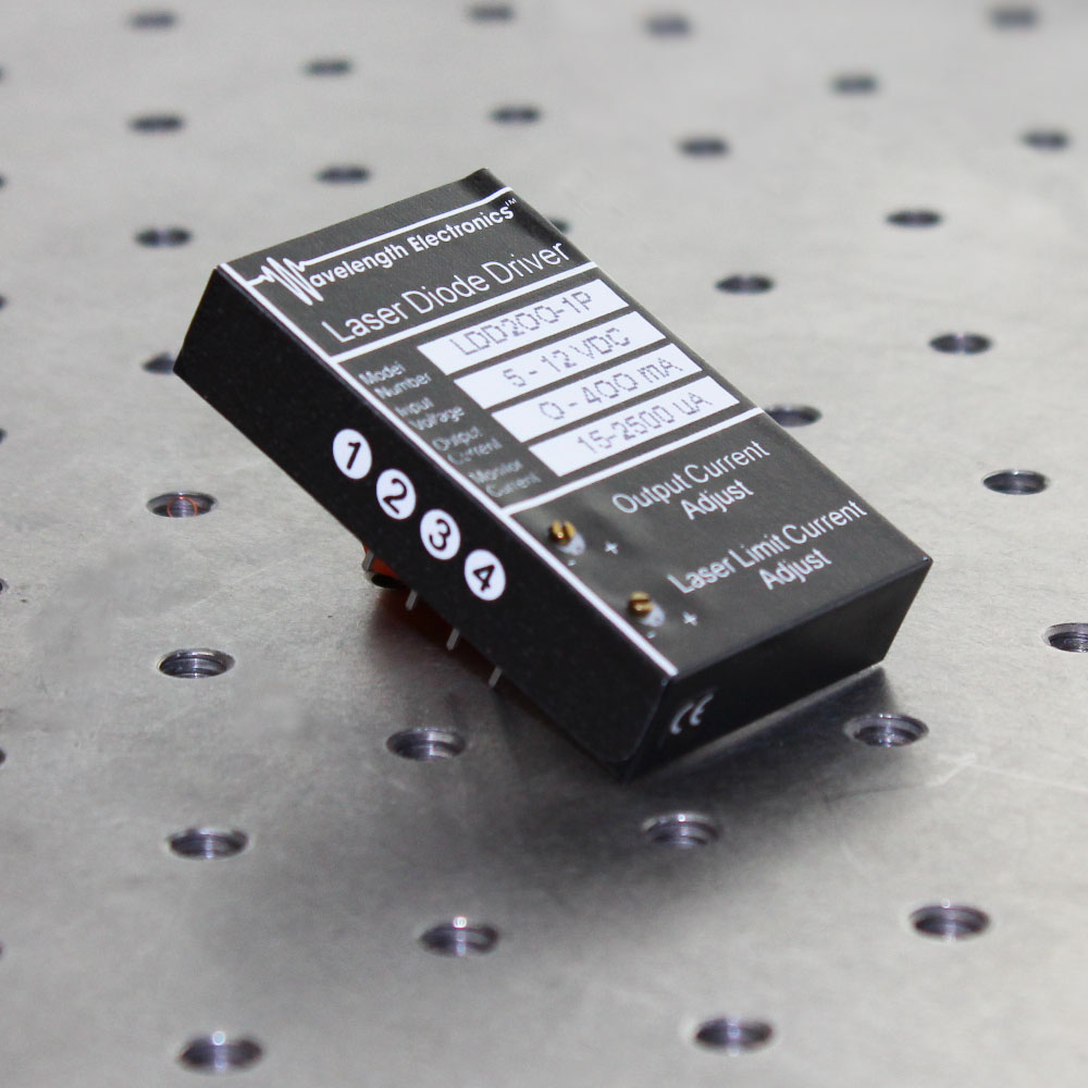
| LDD200 1P OR 2P | LDD200P Series 200 mA Laser Diode Drivers |
$147.00 You save (%) |
 |
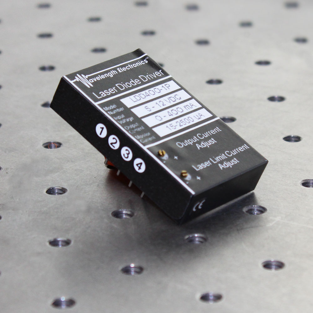
| LDD400 1P OR 2P | LDD400P Series 400 mA Laser Diode Drivers |
$182.00 You save (%) |
 |
| WCB201 | WCB201 Cable for LDD P Series | $37.00 | 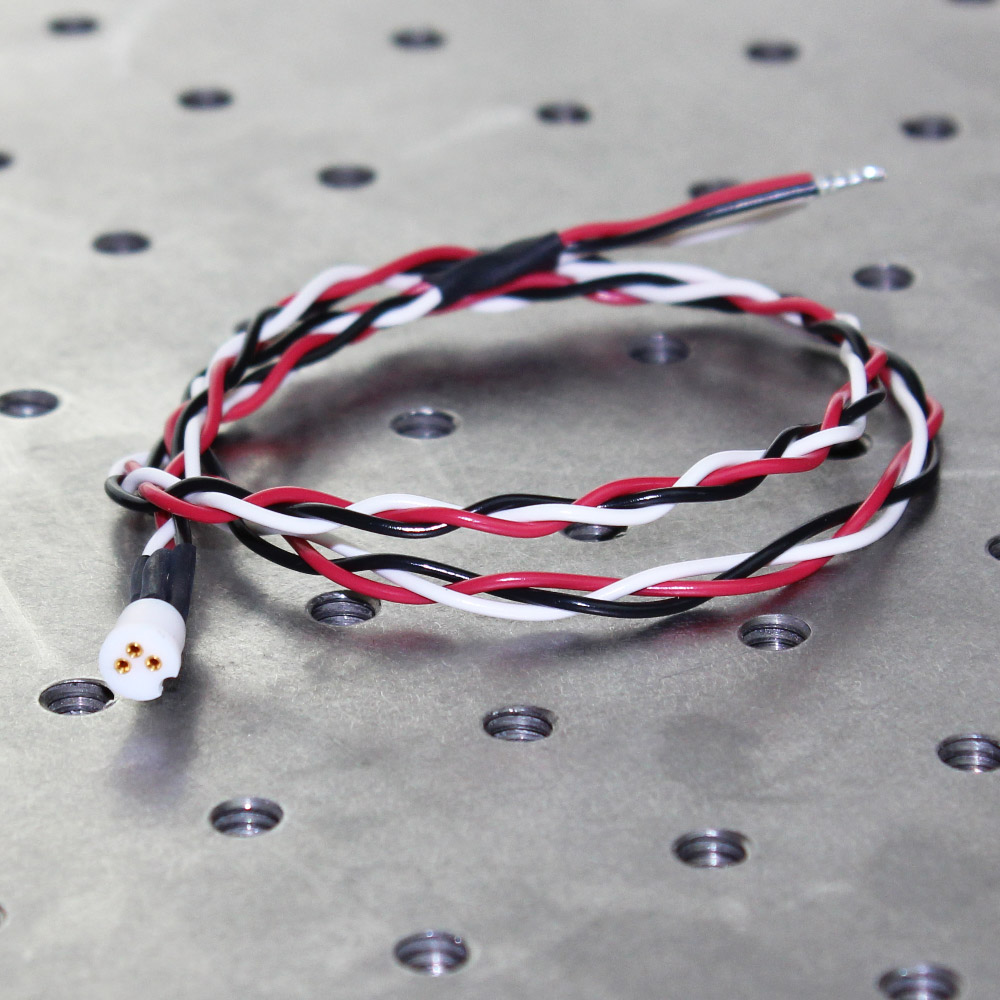 |